Progress on the Überclock
In the last few weeks I've been slowly but steadily advancing on my überclock project. Having a limited amount of spare time, I decided to target simpler intermediate goals for my project. I have a million ideas for possible features I could add to the alarm clock, but I figure it's best to start by implementing a simple, complete, working alarm clock, and later add extra devices to it in a modular fashion. My current plan is to build a black box with configuration buttons, an LCD screen and a little speaker to act as the alarm clock, with an AVR microcontroller for brains.
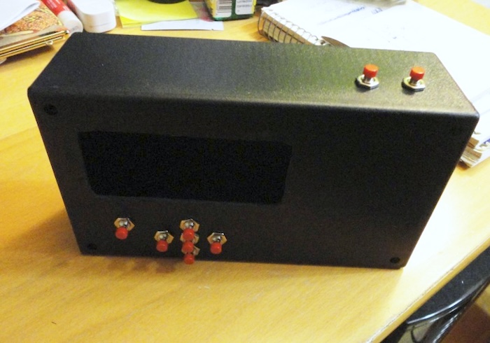
Alarm clock enclosure, a work in progress:
Once I have the simple clock working nicely, I'm thinking I could add infrared emitters to it so that I can have it wirelessly control other devices, such as a large time display panel (a giant 7-segment display), and a white noise machine to help me sleep. One advantage is that this will help me avoid getting discouraging by a project of ever-increasing scope that never gets finished (I should actually be able to finish the first step pretty soon!). Another is that with a modular system, if one part breaks, the rest of the system can potentially continue functioning normally, and the broken part can more easily be fixed.
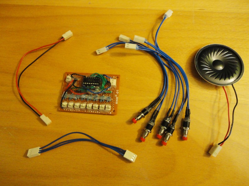
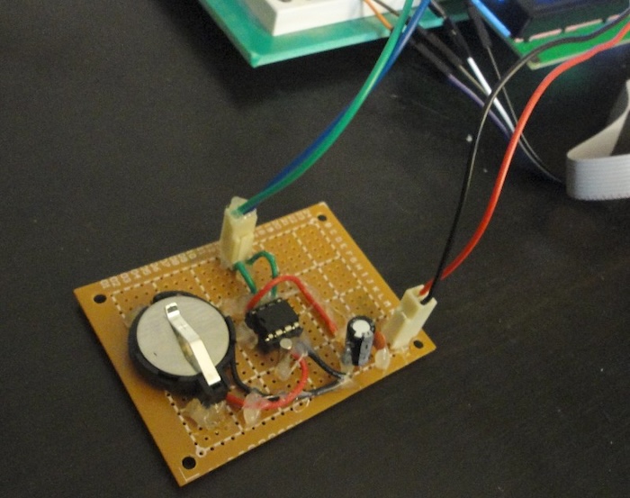
I also decided to build my simple alarm clock itself using a modular design. I've been soldering individual modules on small prototype boards with molex connectors. For example, I've assembled a DS1307 Real-Time Clock (RTC) module with a battery backup, an input module (using a 74HC165 shift register), as well as some pushbuttons and a speakers with molex connectors:
Real-Time Clock module with battery backup:
Input module, pushbuttons and speaker:
Once I complete a power supply module, a few extra pushbuttons with connectors and a main board for the microcontroller, the alarm clock will essentially be complete as far as the hardware goes. The modular design has been particularly advantageous so far because it means I can build and test small components one at a time. If a component is faulty, the problem is easier to track down than if the whole clock was built at once on a large board. I should also say that while my soldering skills have much improved in the last two weeks, I still want to avoid a situation where I would have to painstakingly backtrack out of a soldering mistake.
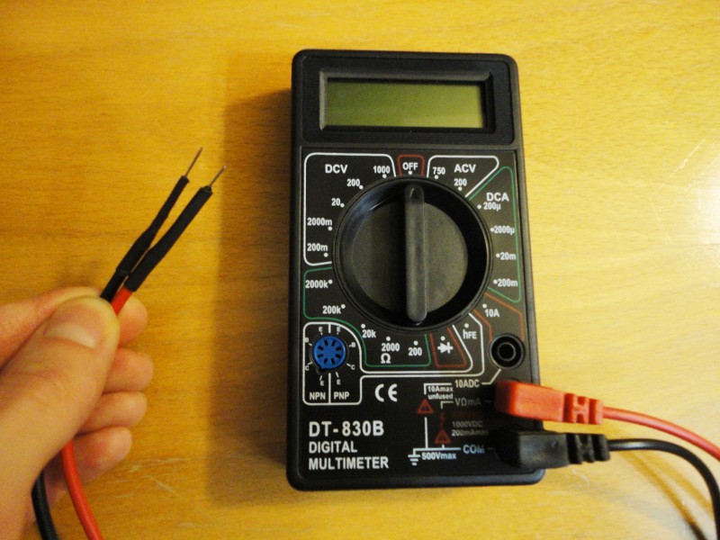
Before I permanently assemble components with solder and hot glue, I try to prototype everything on a breadboard so that I can be sure the final circuit will work properly. One issue I've had is that I often want to use a multimeter to get voltage and current readings, but it's hard to do this reliably with standard multimeter leads. The solution I found was to buy a cheap multimeter on ebay (less than $3 USD shipped, without the 9V battery) and modify the leads so that they can directly connect into the breadboard. I cut off the multimeter leads, soldered some sowing pins at the ends of the wires instead, and wrapped the connection with shrink wrap. I've been very pleased with the result.
Breadboard-ready multimeter leads:
One last thing I'd like to mention is that I found some great online supplier for electronic parts. Tayda Electronics is a store from Thailand which has some pretty amazing prices (2 cents for DIP8 sockets, as low as 4 cents for pushbuttons, etc.) and a very broad inventory. The shipping takes a while (around 3 weeks) but the deals are definitely worth it, especially if you want to stock up on some components. If I need to get some fairly common component quickly, I tend to order from Dipmicro Electronics. They're a Canadian (Ontario-based) store with pretty good prices, sometimes even better than Asian sellers.


