An Inexpensive Robot Platform
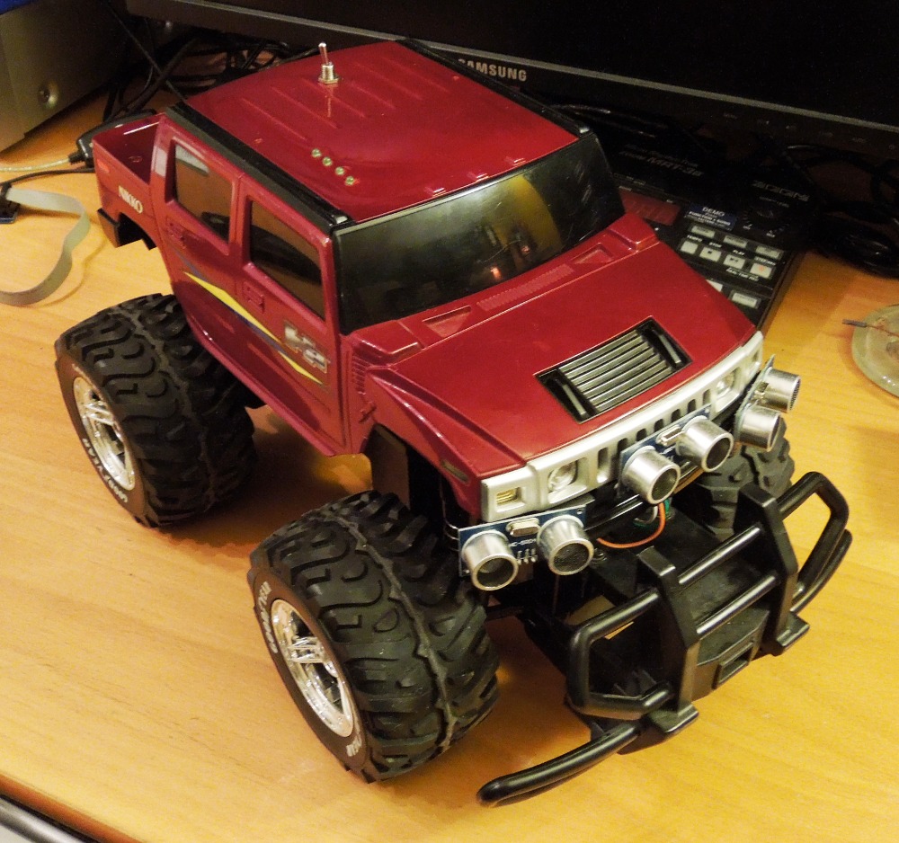
I've been meaning to try building my own small mobile robot for some time. Unfortunately, hobby robotics can get pretty expensive. A simple 4-wheeled robot platform can easily cost 60 to 80 dollars, and that only gets you something big enough to carry batteries, a microcontroller and other small devices. I had this idea that it would perhaps be cheaper to build a robot based on a remote controlled car. RC cars come in a variety of sizes, can handle rough terrain, go pretty fast, and best of all, are often fairly cheap. I was able to find exactly what I needed at the Salvation Army: a used RC truck without the remote control and battery (who needs that?) for the modest sum of $1.99.
For those who want to tinker with microcontrollers, eBay is full of bargains. There are now lots of sellers selling AVR (Atmel) microcontroller boards and Arduino-compatible modules of all kinds at very low prices. For this project, I purchased the following:
-
ATmega64A microcontroller board ($18 shipped)
-
USPasp In-System Programmer for AVR MCUs ($4)
-
H-bridge motor controller module ($7)
-
Bluetooth to RS232 TTL module ($9)
-
4x HC-SR04 ultrasonic rangefinders ($10)
-
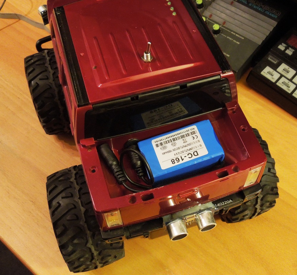
1800mAh Lithium-ion battery and charger ($11)
-
40x 30cm 1p-1p dupont cables ($3)
I also used various components I had on hand, such as small prototyping boards, a 5V power regulator, capacitors, resistors, a ULN2803 transistor array, LEDs, a piezo buzzer, single and dual row pin headers, wires, shrink wrap and 2.1mm male and female power jacks: total value less than $10.
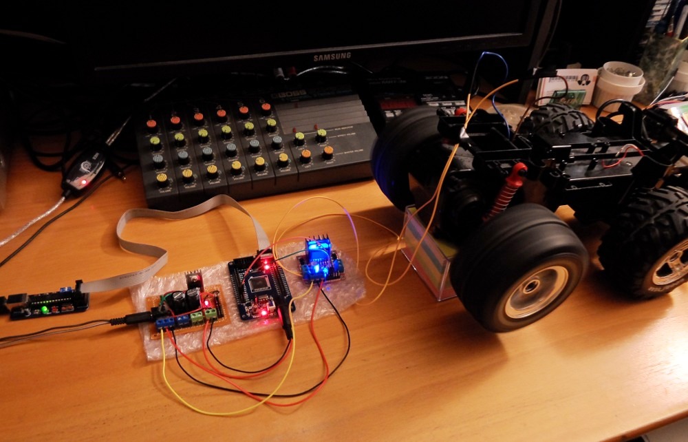
Since I use Linux as my development platform, I went with avr-gcc and avrdude to program the microcontroller. I've had absolutely zero issues so far. Luckily, Ubuntu has preconfigured avr-gcc, avr-libc and avrdude packages in its software repository, which made it very easy to get my setup going.
One thing I would caution newbies about is that AVR chips out of the factory (including the one on my board) run at 1 MHz using their internal oscillator by default. You need to update the MCU's fuse values in order to change this. Before you set the fuse values, the USBasp programmer has a "slow sck" jumper that needs to be enabled. If you don't set this jumper, it will refuse to program the microcontroller or set its fuse values. If you've never used AVR MCUs, I highly recommend ladyada's tutorials.
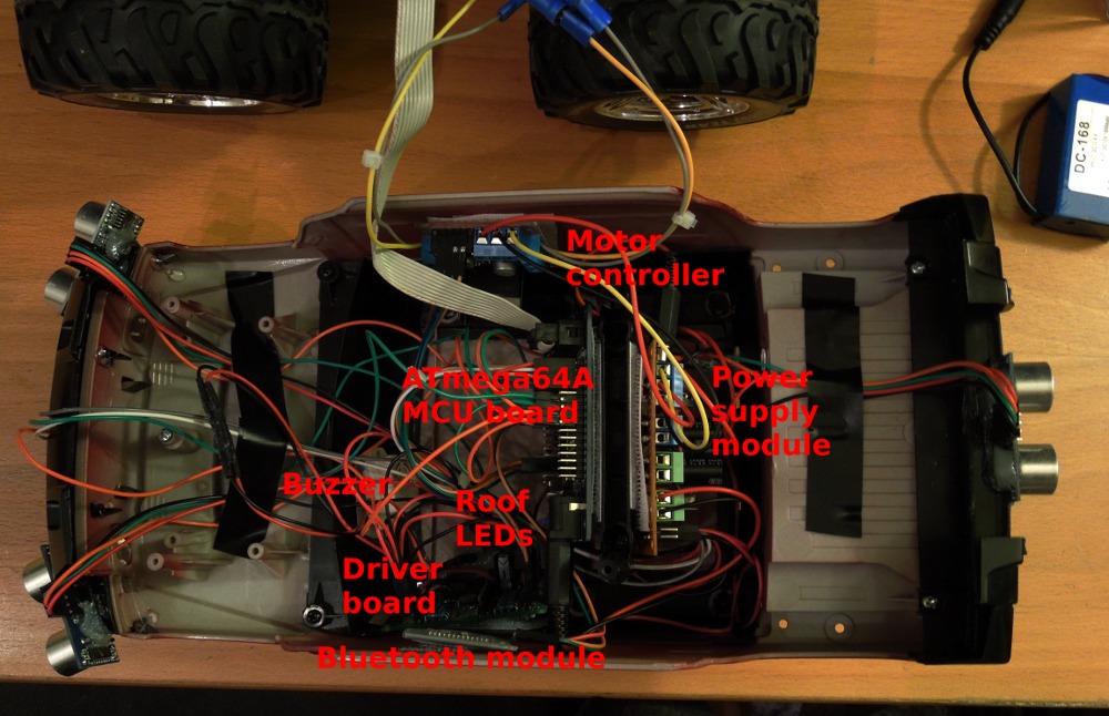
Fortunately, my robot build went very smoothly. I found the components very easy to interface with. The H-bridge controller simply requires two PWM outputs per motor (one for each direction of rotation). The bluetooth module connects directly to the MCU's TX and RX UART ports and creates a serial connection I can interact with using a terminal program. The ultrasonic distance sensors use a two-wire interface where an input is used to trigger an ultrasonic pulse and an output goes low once the echo is received.
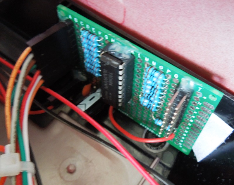
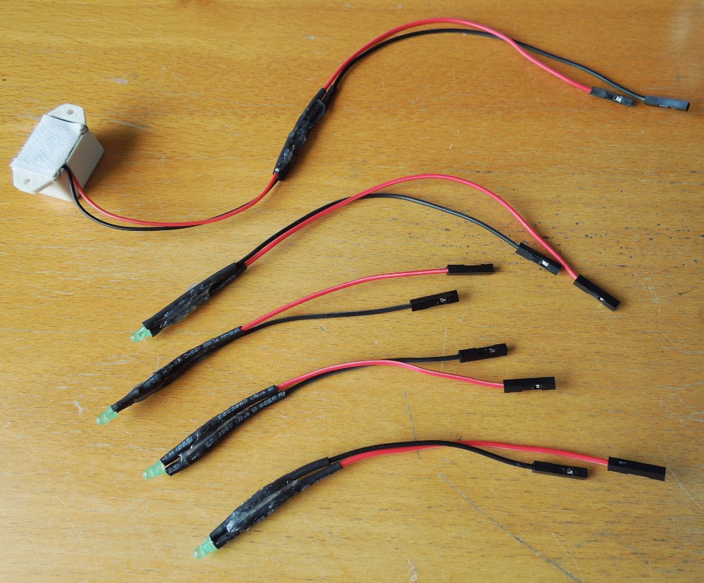
I wanted to add LEDs on the roof of the truck as well as a buzzer module inside so I could present status/debug info in an intuitive way. The LEDs, with a power consumption of 8mA, could have realistically been driven directly from MCU output pins, but the buzzer couldn't, and I wanted to allow switching other devices which consumed more power. My solution to this was to solder a simple module with an ULN2803 driver chip, resistors and some pin headers. The pin headers allow me to use color-coded dupont cables to connect everything (power and IOs), making for easy prototyping.
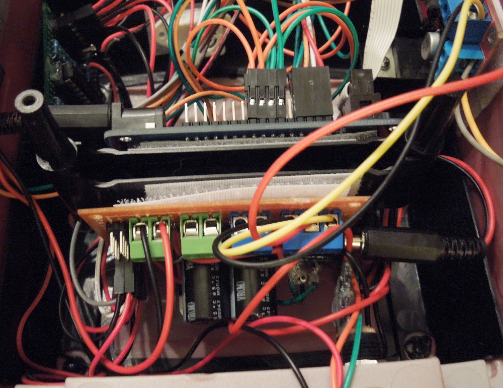
To power all of this, I soldered together a power distribution module. This module hosts some filtering capacitors, a 5V power regulator and various connectors. There is a two-row pin header to distribute regulated 5V to most of the modules, as well as an unregulated 12V output for the motor driver module. I put a 2.1mm female jack in an open back compartment of the truck so that I can plug the lithium-ion battery into there, or an external power supply for testing.
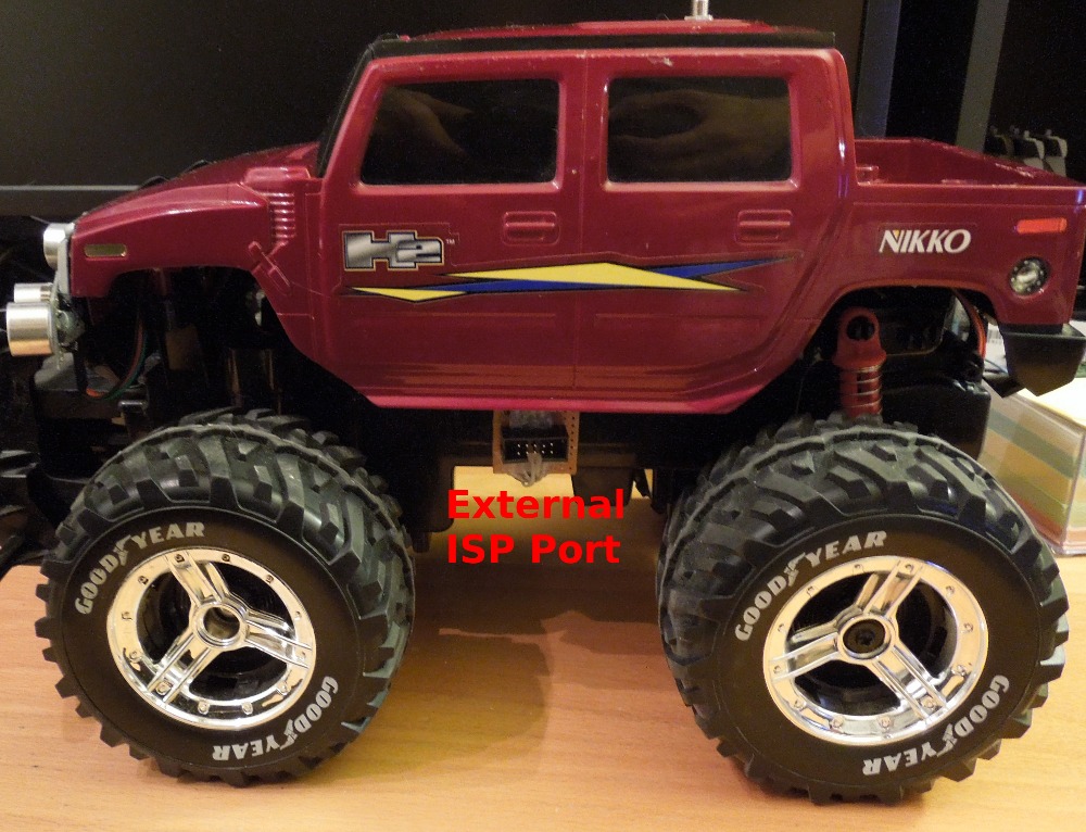
All of the modules are held inside the top part (plastic housing) of the truck using velcro. Because it's still highly inconvenient to remove the cover to program the chip, I soldered an extension for the ISP header of the microcontroller board, and glued it in an accessible location.
This robot doesn't really have much in the way of AI thus far (it only takes commands and reports distance readings over Bluetooth), but I've decided to make the source code available on github. This code should be helpful in understanding how to interface with the components I've used. Possible improvements to be made include the ability to reprogram the MCU through bluetooth.


