Dynamically Adjusting LCD Brightness with Ambient Light
The AVR Alarm Clock has been working reliably for the last few days. My girlfriend, however, pointed out an annoying flaw: the LCD display is extremely bright, probably uncomfortably bright for night time, it would assuredly light up our bedroom with its blinding blue glow. I could make the backlight dimmer by adding a simple resistor, but this would make it harder to read in the daytime. Realistically, I'd like the backlight to be very dim at night time, and near full brightness during the day.
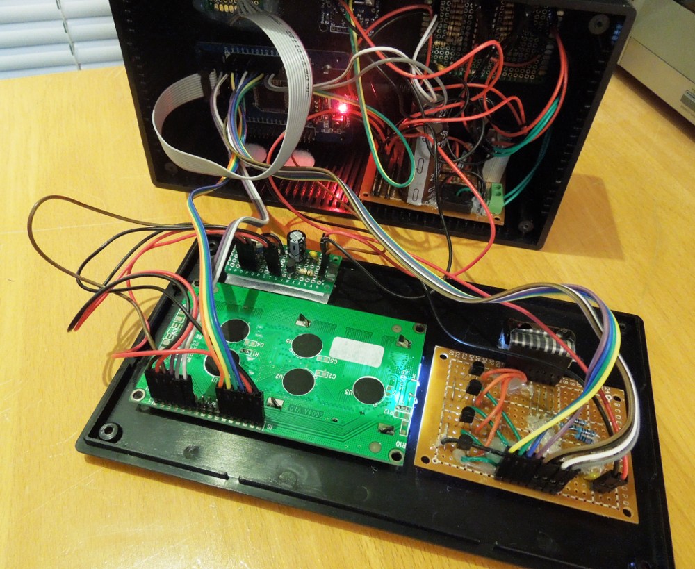
The bad news is, the generic HD44780 LCD I used doesn't have any built-in mechanism to dynamically adjust brightness. Some other affordable LCDs, like the Nokia 5110, allow you to directly control the backlight using Pulse Width Modulation (PWM), but not mine. Fortunately, the LCD backlight uses different power pins from the controller logic, and so, it's very easy to gate the backlight power using a small transistor or mosfet, allowing PWM control of the backlight brightness. I designed a small board to distribute power to the LCD and implement this functionality.
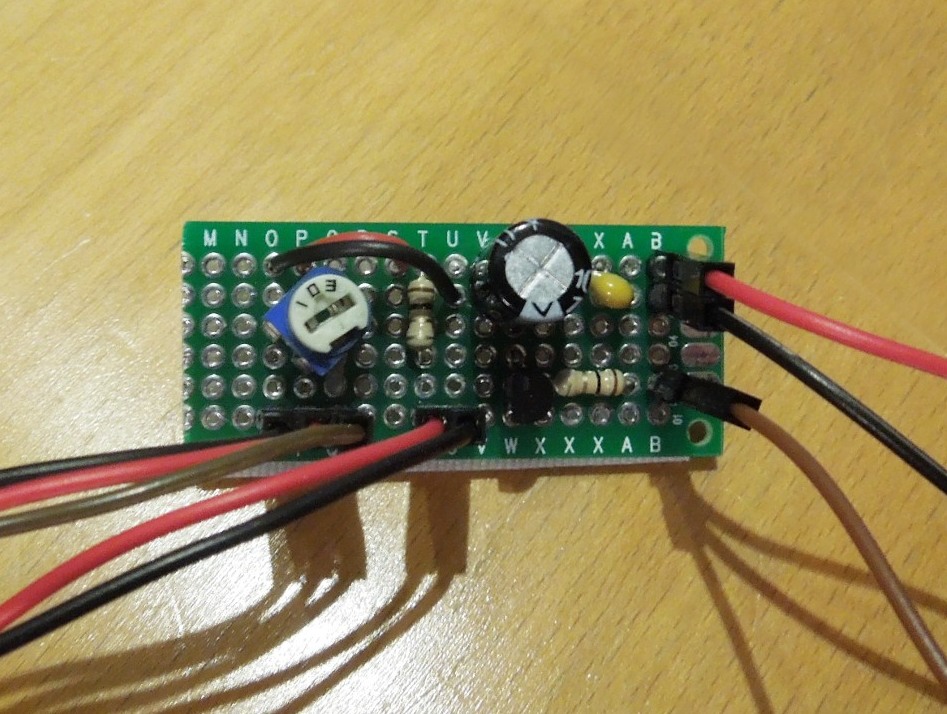
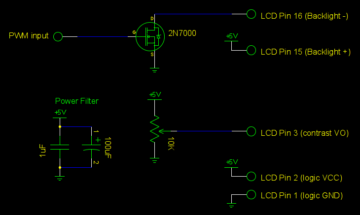
This simple circuit allows easy control of the backlight brightness using a PWM output. I could simply use the time of day to decide how bright the LCD backlight should be. There are issues with this, however. The sun doesn't rise and set at the same time every day, and furthermore, the time of day says nothing about whether the lights are on or off. I decided to take this to the next level and build a light sensor for the AVR clock, so that it could dynamically react to ambient light levels.
I already had several photoresistors on hand. The ones I have produce a resistance reading that varies all the way from ~1KOhms to ~2MOhms (sunlight vs almost complete darkness). This value can be converted to a variable voltage using a simple voltage divider configuration, the voltage can then be read using an Analog to Digital Converter (ADC) input. There is just one problem: the input impedance would be much too high for the ADC to get accurate readings in low light conditions, and unfortunately, low light is where we need the most precision.
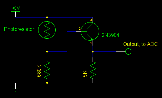
The solution to this problem is to amplify the current from the photoresistor's voltage divider so as to produce a lower impedance output. This could be done with an op-amp chip, but luckily, breadboard prototyping has shown that a simpler and cheaper solution works just fine. I connected a 2N3904 transistor along with a 5K resistor in a common collector amplifier configuration. This allows precise light readings even when all the lights are off in my living room.

I installed the photoresistor in the back-left corner of the top of the alarm clock's casing to prevent the clock's own LEDs from interfering with the light sensor. A few additions to the code and I had the backlight brightness automatically adjusting to ambient light. I made it so that the adjustment is slow and gradual so that moving obstacles (e.g. people) don't result in sudden jumps in brightness.
All modifications to the code are available on github :)


